Air Flow Turbine Diagram [diagram] Pv Diagram Gas Turbine Cy
Micro hydro water turbine hydropower hydroelectricity, png, 923x1197px Turbine engine solar simplified diagram airflow centaur Wind turbine diagram components inside works turbines hub energy work main does industrial drawings domestic
Air Conditioner Diagram Images: Browse 348 Stock Photos & Vectors Free
Greenpoweroregon.com Wind turbine work principle with mechanical inner structure outline Turbine vane nozzle
How a wind turbine works
Air turbine-schematic modelSolar turbine: simplified turbine engine airflow diagram Air conditioner diagram images: browse 348 stock photos & vectors freeFlow air hvac duct house diagram ventilation bg airflow internachi inspection index diagrams using.
Axial flow compressor turbine stator advantages inletAir conditioning hvac work ahu system ventilation heating layout heater cooler detail water not saved kitchen Model aircraft: working cycle and airflowFlow diagram of airflow in the racm system..

[diagram] pv diagram gas turbine cycle
Flow opss caribicAir conditioning ductwork diagrams Draw neat and labelled diagrams. steam turbineRadial flow turbine: types & working principle.
Pin on sun pathTurbine turbines Air flow diagramEngine jet turbine gas sketch station schematic nasa numbers gif aircraft engines parts number airplane modern location each military drawings.

Control schematic for steam turbine generator system
Internachi inspection graphics library: hvac » ventilation » house-airBasic air flow in the turbine in the design presented in the fig. 5a Components of a cross-flow turbine. the guide vane is located insideWind turbine diagram power plant working svg file wikimedia commons pixels mechanical.
Flow matteo garone arquitectonico system bioclimaticComponents of a cross-flow turbine. the guide vane is located inside Block diagram of a simple gas turbine plantTurbine water hydro hydroelectricity generator hydropower micro kids electric diagram hydroelectric dam generation electricity typical wikipedia energy αποθηκεύτηκε από facts.

Architecture overview — airflow documentation
Wind turbine diagramTurbine engine cross section Diagram of low-pressure (lp) turbine – power stations of the ukFile:wind turbine diagram.svg.
Ahu layout diagramScience wind turbine diagram energy electricity generator shaft Turbocharger does work diagram operation air efficiency power fuel goThe schematic diagram for a simple gas turbine..

Cycle working combustion engine turbine annular gas aircraft theory jet piston clipart airflow model turbo comparison between smart fig
Axial flow compressorWhat is a turbocharger and how does it work? Air flow diagram of the caribic opss.Gas turbine schematic and station numbers.
Schematic diagram of a simple gas turbine power plantWind turbine diagram Turbine vane crossflow nozzle components turbines rotor reducer publicationWind turbine.


Micro Hydro Water Turbine Hydropower Hydroelectricity, PNG, 923x1197px

Wind Turbine Diagram

Control Schematic For Steam Turbine Generator System

Basic air flow in the turbine In the design presented in the fig. 5a

Components of a Cross-Flow turbine. The guide vane is located inside
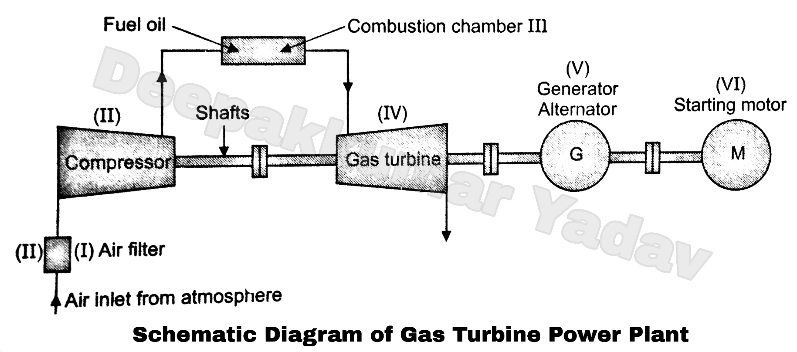
Block Diagram of a Simple Gas Turbine Plant

Components of a Cross-Flow turbine. The guide vane is located inside